Test Equipment
المقالات >
Test Equipment
LUOBME

Electrical Safety Analyzer & Test Equipment
Description and Purpose
Test equipment refers to any equipment that a biomedical engineer or a technician uses to perform calibration of medical devices. The electrical safety analyzer is one of the most important devices used to inspect medical equipment and perform regular maintenance to meet the safety standards required to protect the patients and the end-user in the medical field and avoid dangers resulting from electrical faults [1]. It is used to perform various electrical safety tests, including ground continuity test, insulation test, high voltage test, and line leakage test, to check that the device under test complies with electrical safety requirements [2].
Leader Manufacturer
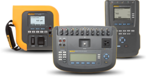
Figure 1. FLUKE’s Electrical Safety Analyzers.
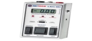
Figure 2. NETECH’s Electrical Safety Analyzer.
Principle of Operation
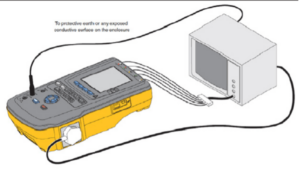
Figure 3. General connections to an electrical safety analyzer.
To start using the electrical safety analyzer, follow the steps below:
- Preparation and connection
- Ensure the device connectivity to the power source.
- Connect the device to the electrical safety analyzer.
- Basic safety tests
- Turn on the electrical safety analyzer and follow the settings recommended by the manufacturer appropriately.
- Perform tests such as, the ground continuity test, which is the resistance of the protective earth conductor that is measured between the earth pin on the mains plug and the protectively earthed point on the equipment enclosure. The reading should not exceed 0.2 ohm at any such point. According to the International Electrotechnical Commission (IEC) 60601, the test is conducted using a 50Hz current between 10A and 25A for 5 seconds.
- Insulation Resistance Test: Applies a lower DC voltage across different parts of the electronic design, eventually, the results are displayed in Mega Ohm.
- Earth Leakage Current: The current that normally flows in the earth conductor of a protectively earthed piece of equipment, 5mA in normal conditions.[3]
- Patient Leakage Current: Under IEC 60601-1, for class I and class II type B and BF equipment, the patient leakage current is measured from all connected parts having the same work associated together and true earth. For type CF equipment the current is measured from each connected portion in turn and the leakage current leakage must not be surpassed at any connected portion.
- Monitor readings and standards:
- Read the values displayed on the analyzer screen.
- Ensure that the values comply with the specified standards, such as The National Fire Protection Association (NFPA 99).
- Results Documentation
- Record results and observations accurately [3].
UV Light Test meter
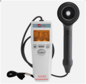
Figure 4. UV Light Test Meter.
Description and Purpose
A UV (Ultra Violet) light test meter, sometimes referred to as a UV radiometer or UV light meter, is a specialized device that measures the intensity and amount of UV radiation. It is a crucial device to obtain accurate intensity control and deliver the appropriate dosage for treatment or disinfection. Different UV wavelengths are used in different medical applications, for instance sterilizing, and UV therapy. The main purpose of the UV test meter is to ensure and verify that the specific UV power is delivered which includes the intensity and wavelength. Since the healthcare provider uses UV light widely, the UV meter provides helpful information about the consistency of UV light during the desired time. UV light meter is also used to ensure that there is no extra exposure outside the desired area [4], [5].
Principle of operations
The UV meter is especially designed to detect the UV light. The UV sensor is the core component that is responsible for detecting the incidents UV light. The sensor is made of a material that is highly sensitive to UV radiation such as silicon carbide (SiC) or gallium nitride (GaN). [6] When the incident light hits the sensor, the electric current is generated due to the photoelectric effect. In more detail, the energy of the UV light photons is transferred to the electrons in the sensor’s material. As a result, the flow of electrons occurs, and the electric current, which is proportional to the UV light intensity, is generated. After that, the signal processing amplifies, filters, and converts the electric current into readable analog or digital data. The data is mostly presented in microwatts per square centimeter (µW/cm²) or milliwatts per square centimeter (mW/cm²) [4]-[6].
Leader manufacturers
- International Light Technologies (ILT)
- Hönle Group, Spectro-UV
- Linshang Technology
Particle Counter
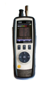
Figure 5. CEM Particle Counter.
Description and purpose
Particle counters are capable of detecting and counting particles in the air, liquids, or surfaces. A particle counter is a crucial tool used in clean-room operations to monitor, classify, and diagnose contamination sources. Thus, it detects and counts physical particles in all clean rooms to maintain a particular level of cleanliness [7].
Principal of operation
Aerosol particle counters come in two varieties: optical and condensation. Optical particle counters can identify particles within fluids and in the air. An intense light source is used to count and measure particles when the light source is obscured. This particular monitoring equipment measures airborne particles utilizing the technique of light scattering. Moreover, an optical particle can use direct imaging, light scattering, and light-blocking techniques to identify and quantify particles [7].
A condensation particle counter controls the saturation levels as they change with temperature by using isopropyl alcohol or butanol to expand the entered particles up to 200%, making detection easier. Technicians can use this monitoring gadget to find particles as small as 2 nm, which is insufficient for an optical particle counter to detect. These devices, which are hand-held and have a reduced flow rate for spot-checking and certifying smaller amounts of air, are perfect to use inside clean rooms. For constant monitoring of higher air volumes in clean rooms, a large portable condensation particle counter can be used [7].
Leader manufacturers
- Beckman Coulter
- TSI Incorporated
- Particle Measuring Systems
Vibration Reader
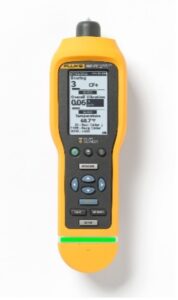
Figure 6. FLUKE’s Vibration Reader Device.
Description and Purpose
A vibration reader, commonly referred to as a vibration analyzer, is a device used to assess and interpret vibrations within mechanical systems. Its primary function is to monitor these systems for proper operation and to detect issues such as misalignment or bearing defects [8].
The key purpose of a vibration reader is to identify early indicators of mechanical issues, thus enabling predictive maintenance, minimizing downtime, and reducing repair expenses [9].
Leader Manufacturers
- SKF
- Fluke
- Brüel & Kjær.
Principle of Operation
Vibration readers generally utilize piezoelectric accelerometers, which convert mechanical vibrations into electrical signals. These signals are subsequently processed, analyzed, and displayed. Many devices use Fast Fourier Transform (FFT) analysis to convert these signals into frequency-domain data, assisting in the detection of specific vibration-related problems [9], [10].
Digital Pressure Meters
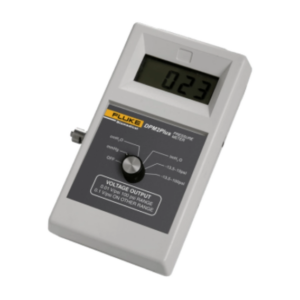
Figure 8. FLUKE’s Digital Pressure Meter.
Description and Purpose
A digital pressure meter (DPM) is designed to test a variety of medical equipment such as ophthalmology devices, lasers, dialysis machines, and surgical suction tools. It measures the medical equipment’s positive and negative pressures in liquid or gaseous form. [11]
Digital pressure meter (DPM) is mainly used for the following:
- Examining the static and variable cuff pressures of noninvasive blood pressure monitors, sphygmomanometers, and pneumatic tourniquets.
- Determining the positive pressure at which compressor pumps, respirators, and ventilators operate.
- Verifying the operation, purge, and occlusion pressures in volumetric infusion pumps.
- Confirming negative pressures in suction devices used for surgery and diagnostics, such as thermotic drainage.
- Inspecting the vacuum levels in irrigation and extraction devices used in eye surgery.
- Verifying the dialysate pressure in renal dialysis equipment.
- Using a strip chart recorder to capture the output in order to maintain long-term records of the applied pressure against voltage [12].
Leader Manufacturers
- Fluke
- WIKA
- Omega Engineering.
Principle of Operation
The pressure within a system or area is converted to an electronic signal through efficient measuring cells with electronic linearization of the characteristic curve. Eventually, this signal is sent to a digital display [13], [14].
Patient Monitor Simulator

Figure 9. FLUKE’s Different types of Patient Monitor Simulator.
Description and Purpose
Patient simulators, often referred to as physiological simulators or vital sign rhythm generators, are one of the most common and important instruments used by biomedical technicians. Patient simulators are used to precisely test and confirm the functionality of patient monitoring devices, including ECG machines, cardiac monitors, and vital signs monitors. Patient simulator devices simulate various physiological characteristics like blood pressure, respiration, temperature, arrhythmia waveforms, and ECG. These physiological characteristics are measured by the device being tested. Hence, the accuracy of the patient monitor is determined and fixed if necessary. Furthermore, these simulators are able to evaluate the speed at which the patient monitor reacts to modifications in the patient’s state [15], [16].
Leader Manufacturers
- Fluke
- Philips
- Dräger
Principle of Operation
The patient monitor device being tested is connected to the multi-parameter simulator using an extension cable or ECG wires. Once the required parameter has been selected, the patient monitor simulator replicates or simulates the desired function by delivering electrical impulses. The numbers in the patient monitor are compared with the measurements taken by the simulator and perform calibration if needed [15].
Tachometer
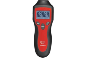
Figure 10. A Contactless Tachometer.
Description and purpose
A tachometer, also known as a revolution counter or RPM gauge. It is a device utilized to measure the rotational speed of a moving object, such as a disc or shaft, quantifying revolutions per minute (RPM). It is essential for performing tests, measurements, and maintenance of laboratory equipment [17], [18].
Leader Manufacturers
- Extech
- Carlo Gavazzi
- Honeywell
Principle of Operation
Although there are various types of tachometers in the market, they function similarly. The electric tachometer is the most used typical type which operates according to the principle of relative motion between the magnetic field and the shaft of the connected device. The tachometer’s motor functions as a generator, producing voltage according to the shaft’s velocity. It measures the number of rotations the crankshaft completes per minute. Knowing the engine’s RPM and operating range is crucial to prevent unnecessary damage. It can function on either alternating or direct current [18].
Gas Flow Analyzer
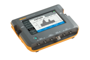
Figure 11. FLUKE’s Gas Flow Analyzer.
Description and purpose
A gas flow analyzer is a critical instrument used in biomedical applications to measure the gas flow rate of medical devices like ventilators, and this ensures precise delivery of gases, optimizing treatment and diagnosis by maintaining appropriate gas levels for patient needs across various medical equipment, including aspirators, suction devices, anesthesia machines, particular patient monitor parameters, and insufflators [19], [20].
Leader Manufacturers
- Fluke Biomedical
- Draegerwerk AG & Co.
- KGaA, Maxtec LLC
Principle of Operation
There are multiple gas flow analyzers in the market, however, measuring the pressure and the gas flow is an essential function in all of these devices, i.e., as these devices contain a pressure meter and a flow sensor/ meter within their components. Furthermore, although each type has its working principle, e.g., zirconia oxygen analysis, hydrogen purity analysis, and infrared gas analysis, they all operate by utilizing the gas’s optical properties. The infrared gas analyzer, for instance, detects a gas amount by measuring the absorption levels in an air sample. It determines the amount of infrared light the sample absorbs. If a specific gas is abundant, more light will be absorbed at a particular frequency [20], [21].
Electrosurgery Analyzer
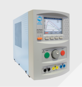
Figure 12. Electrosurgery Analyzer
Description and Purpose
Electrosurgical units (ESUs) use high-frequency electrical currents to cut tissue and control bleeding by causing blood to coagulate. In order to guarantee dependable operation and the best possible surgical results, the Electrosurgery Analyzer is essential to evaluate the ESU’s efficacy and safety. The analyzer measures critical parameters such as power output, current, voltage, and frequency to ensure that the ESU follows the manufacturer’s guidelines which confirms optimal results [22].
Principle of Operation
- Power On
- Switch on the analyzer to start up the device and ensure the display is operational.
- Connect Test Leads
- Attach the appropriate test leads between the Electrosurgical Unit (ESU) and the analyzer, ensuring secure connections.
- Set Test Load
- Adjust the test load resistance on the analyzer to the desired value using the control buttons.
- Confirm the setting on the display.
- Perform Tests
- Generator Output Tests: Connect the necessary leads, set the test load, and initiate the test.
- Contact Quality Monitor (CQM) Test: Attach the CQM leads and monitor for any alarms indicating loss of contact.
- High frequency (HF) Leakage Current Test: Connect the appropriate leads, set the analyzer to measure leakage current, and initiate the test.[23]
Leader Manufacturers
- Testa Center
- Fluke Biomedical
Defibrillator Analyzer
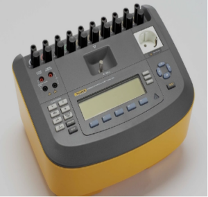
Figure 13. FLUKE’s Defibrillator Analyzer.
Description and Purpose
Defibrillator analyzers are vital medical devices that are used to restore a normal heart rhythm during cardiac arrest. A defibrillator analyzer is a specialized piece of equipment made to test and ensure that defibrillators are operating properly.[24] The defibrillator performance parameters that need to be tested include at least four: automatic external defibrillation, synchronized-mode operation, discharge energy, and ECG monitoring.[25] The analyzer’s purpose, regardless of the defibrillator’s type, automatic, semi-automatic, pulsed biphasic, and monophasic outputs, is to inspect the defibrillator’s capabilities and confirm it meets manufacturer requirements. The device’s output energy is measured using analyzers [26].
Principle of Operation
- Energy Testing
- Configure the Analyzer: Set the analyzer to the energy test mode.
- Connect the Defibrillator: Attach the defibrillator using the designated input connectors.
- Start the Test: Activate the energy test function.
- Verify and Charge: Confirm waveform settings and charge the defibrillator.
- Discharge: Press the discharge button and review the energy delivered in Joules as displayed by the analyzer.
- Synchronization Testing
- Configure the Analyzer: Set the analyzer for synchronization testing.
- Prepare the Defibrillator: Switch the defibrillator to synchronous mode.
- Sync with ECG: Ensure the defibrillator’s pulse aligns with the ECG heart rate.
- Measure Synchronization Time: Record the interval between the ECG ‘R’ wave and the defibrillator pulse.
- Charge Time Testing
- Configure the Analyzer: Set the analyzer to measure charge time.
- Prepare the Defibrillator: Fully discharge the defibrillator before starting.
- Start the Test: Begin the charge time procedure.
- Measure Charge Time: Time how long it takes for the defibrillator to reach the specified charge level [27].
Leader Manufacturers
- TE Connectivity (TE Connectivity Ltd).
- Fluke Biomedical.
- Rigel Medical.
Incubator Radiant Warmer Analyzer

Figure 14. Incubator radiant warmer analyzer.
Description and Purpose
The incubator radiant warmer analyzer is used as a portable device designed to confirm the appropriate operation and environment of infant incubators. This unit records parameters important to the care of infants over time, such as temperature, sound level, airflow, and relative humidity to ensure the baby’s safety, which requires regular preventive maintenance tests [28], [29].
Leader Manufacturers
- Fluke Biomedical
- Datrend Systems Inc
Principle of Operation
The incubator radiant warmer analyzer is a crucial tool, capable of measuring various parameters such as humidity, airflow, sound, and temperature. It consists of different sensors, each responsible for measuring one of the parameters. After collecting the data from the sensors, the device analyzes and correlates them to evaluate the performance of the incubator and radiant warmer. The analyzer contains an LCD screen for real-time data and test results [30].
Medical ScopeMeter “Portable Oscilloscope”
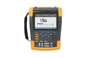
Figure 15. Medical ScopeMeter “Portable Oscilloscope”.
Description and Purpose
The ScopeMeter is a portable, high-performance oscilloscope designed for industrial and field-based troubleshooting. It offers comprehensive capabilities for capturing, displaying, and analysing electrical waveforms, making it an essential tool for diagnosing issues in various systems [31].
Principle of Operation
- Power On and Signal Connection
- Power on the ScopeMeter and ensure it is connected to a power source.
- Connect voltage probes to the test points of the equipment under measurement.
- Oscilloscope Mode and Waveform Adjustment
- Select the oscilloscope mode to display waveforms.
- Adjust the vertical and horizontal scales to optimize the view of the captured signals.
- Measurement and Analysis
- Utilize the ScopeMeter’s measurement functions (voltage, current, frequency, etc.) to analyze the signals.
- Additional Functions (if applicable)
- Utilize the multimeter mode for basic electrical measurements and leverage advanced features such as automated measurements, math functions, and waveform comparison for in-depth analysis, as applicable.
- Utilize data logging and trending features to monitor changes or intermittent issues over time.
- Power Off
- After finishing testing and analysis, press the power button to turn off the ScopeMeter.
- Ensure the device is properly stored and the voltage probes are disconnected [31]-[33].
Leader manufacturers
- Fluke
- GAOTek
- RIGOL
Phototherapy Radiometer
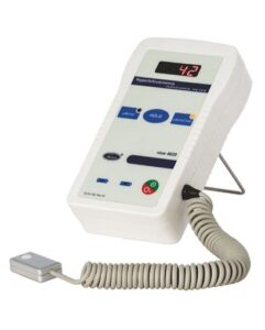
Figure 16. Phototherapy Radiometer.
Description and Purpose
Phototherapy radiometers measure the light intensity in the blue spectrum to ensure accurate and effective neonatal phototherapy treatment. These devices help adjust the light intensity for optimal treatment results.
Hand-held radiometers are essential tools for checking the output of neonatal phototherapy devices. They can be easily integrated into routine maintenance and output monitoring programs. Evaluating the wavelength and angular response of different radiometers and comparing these with phototherapy light source spectrum analysis ensures accurate and effective monitoring [34].
The Phototherapy Radiometer is designed to precisely detect light radiation in the blue region of the spectrum, ranging from 429 to 473 nanometers. This specific spectrum is used to treat hyperbilirubinemia in newborn children [35].
Leader Manufacturers
- FLUKE
- Olidef Medical
- Natus
Principle of Operation
Phototherapy radiometers function by detecting and precisely measuring the intensity of blue light radiation within the wavelength range of 425nm to 475nm. These devices utilize sensors to convert detected light into electrical signals, which are processed to provide accurate measurements of light intensity, typically expressed in units like μW/cm². Calibration ensures these measurements are reliable, allowing healthcare providers to adjust phototherapy devices to deliver optimal treatment outcomes [36].
References
[1] Medical Electrical Safety Analyzer | Fluke Biomedical. (n.d.). Fluke Biomedical. https://www.flukebiomedical.com/products/biomedical-test-equipment/electrical-safety-analyzers
[2] Biomedical Test Equipment – Netech Corporation. (n.d.).
https://www.netechbiomedical.com/electrical-safety-analyzers
[3] Davies, H. (n.d.). Electrical safety tests. EBME. https://www.ebme.co.uk/articles/electrical-safety/electrical-safety-tests
[4] What is a UV sensor? (no date) Davis Instruments. Available at: https://www.davisinstruments.com/pages/what-is-a-uv-sensor.
[5] How to Select the Best UV Light Meter For Your Application?. (2020, April 2). Transmission Meter | UV Light Meter | Coating Thickness Gauge – Linshang. https://www.linshangtech.com/tech/how-to-select-the-best-uv-light-meter-for-your-application-tech1166.html
[6] understanding What is UV Sensor and how UV Sensor work? (n.d.). haisenuvc.com. https://www.haisenuvc.com/what-is-uv-sensor/
[7] Frank, “What is a particle counter and how does it work?: Laboratory supplies,” Lab Supply Network, https://www.laboratory-supply.net/blog/what-is-a-particle-counter-and-how-does-it-work/
[8] SKF. “Vibration Meters.” Skf.com, 2024, www.skf.com/au/products/condition-monitoring-systems/portable-systems..
[9] National Instruments. Piezoelectric Accelerometer. www.researchgate.net/figure/a-National-Instruments-cDAQ-9191-wireless-data-acquisition-unit-and-NI-9234-sound-and_fig2_334378888.
[10] Brüel & Kjær. “FFT Analyzer App | BZ-7230 | Brüel & Kjær.” Bksv.com, Brüel & Kjær | B&K | Sound and Vibration, 2024, www.bksv.com/en/instruments/handheld/sound-level-meter-apps/bz-7230-fft-analysis.
[11]“DPM2Plus Universal Pressure Meter Tester | Fluke Biomedical,” www.flukebiomedical.com. https://www.flukebiomedical.com/products/biomedical-test-equipment/digital-pressure-meters/dpm2plus-universal-pressure-meter
[12]Manual, “DPM2 Plus Digital Pressure Meter,” 2006. Available: https://www.flukebiomedical.com/sites/default/files/dpm2plusomeng0000.pdf
[13]“Digital Pressure Meter,” labcompare. https://www.labcompare.com/Materials-Research-and-Metallurgical-Equipment/26848-Digital-Pressure-Meter/
[14]“Digital pressure gauges calibration – Product overview – WIKA Saudi Arabia,” www.wika.sa. https://www.wika.sa/products_digital_pressure_gauges_calibration_en_co.WIKA
[15] “Biomedical Test Equipment – Netech Corporation,” www.netechbiomedical.com. https://www.netechbiomedical.com/products/patient-simulators
[16] “Multiparameter Patient Simulator and it’s Benefits,” Biometriccables, Sep. 27, 2023. https://www.biometriccables.in/blogs/blog/multiparameter-patient-simulator-and-its-benefits#
[17] Tachometers – A Complete Guide, https://uk.rs-online.com/web/content/discovery/ideas-and-advice/tachometers-guide (accessed Jun. 3, 2024).
[18] What is tachometer and its uses?, https://www.shakedeal.com/blog/what-is-tachometer-and-its-uses/ (accessed Jun. 3, 2024).
[19] “Category: Flow measurement,” BiomedicalBlog, https://biomedical.blog/category/flow-measurement/ (accessed Jun. 3, 2024).
[20] Gas-flow analyzers | biomedical instrumentation & technology, https://meridian.allenpress.com/bit/article/39/1/43/198540/Gas-Flow-Analyzers (accessed Jun. 3, 2024).
[21] Australian Dynamic Technologies, “How do gas analysers work?,” Australian Dynamic Technologies, https://www.austdynatech.com.au/how-do-gas-analysers-work/ (accessed Jun. 3, 2024).
[22] Fluke Biomedical, “Electrosurgical Analyzer Primer,” pp. 1-12, [Online]. Available: https://www.flukebiomedical.com/sites/default/files/6013240-en-electrosurgical-analyzer-primer-an-w_0.pdf. [Accessed: Aug. 1, 2024].
[23] Fluke Biomedical, RF303 Electrosurgical Analyzer Operating Manual, Rev. 1.1, 2015. [Online]. Available: chrome-extension://efaidnbmnnnibpcajpcglclefindmkaj/https://www.flukebiomedical.com/sites/default/files/resources/rf303_omeng0000.pdf. [Accessed: Jul. 31, 2024].
[24] Calibration of Defibrillator Analyzer by Voltage Square Method. [Online]. Available: https://www.researchgate.net/publication/329254652_Calibration_of_Defibrillator_Analyzer_by_Voltage_Square_Method. [Accessed: May 28, 2024].
[25] PubMed, “[Defibrillator analyzer],” PubMed, [Online]. Available: https://pubmed.ncbi.nlm.nih.gov/10604089/. [Accessed: Jul. 30, 2024].
[26] Fluke Biomedical, “Importance of Defibrillator Testing,” Fluke Biomedical, [Online]. Available: https://www.flukebiomedical.com/blog/importance-defibrillator-testing. [Accessed: Jul. 30, 2024].
[27] Fluke Biomedical, “7000 DP Defibrillator Analyzer User Manual,” [Online]. Available: https://www.flukebiomedical.com/sites/default/files/7000dp_umeng0100.pdf. [Accessed: 31-Jul-2024].
[28] Incu Incubator Analyzer Operators Manual – Frank’s Hospital …, http://frankshospitalworkshop.com/equipment/documents/workshop_equipment/manuals/Fluke INCU Incubator Analyzer – User manual.pdf (accessed Jun. 7, 2024).
[29] “Products,” Infant Incubator Analyzer | Fluke Biomedical, https://www.flukebiomedical.com/products/biomedical-test-equipment/incubator-radiant-warmer-analyzers (accessed Jun. 8, 2024).
[30] Set-up Guide: INCU II Incubator/Radiant Warmer Analyzer, https://www.flukebiomedical.com/sites/default/files/resources/INCUII_QG_A_W.PDF (accessed Jun. 8, 2024).
[31] Fluke-direct. Available at: https://www.fluke-direct.com/pdfs/cache/www.fluke-direct.com/190-204-am/manual/190-204-am-manual.pdf (Accessed: June 11 2024).
[32] Fluke ScopeMeter 2B/2M User Manual [Online]. Available: https://assets.fluke.com/manuals/scopemt2umeng0000.pdf.
[33] Working Principle of an Oscilloscope [Online]. Available: https://www.tutorialspoint.com/working-principle-of-an-oscilloscope.
[34]“PHOTOTHERAPY RADIOMETER – RAY (Phototherapy Irradiance meter) – http://www.niceneotech.com/blog/,” May 06, 2019. https://www.niceneotech.com/blog/2019/05/06/ray-nice-4020-phototherapy-radiometer/ (accessed Jun. 06, 2024).
[35] “DALE40 Phototherapy Radiometer | Fluke Biomedical,” www.flukebiomedical.com. https://www.flukebiomedical.com/products/biomedical-test-equipment/phototherapy-radiometers/dale40-phototherapy-radiometer
[36] Researchgate.net. [Online]. Available: https://www.researchgate.net/publication/334643109_Phototherapy_Radiometer_with_AS7262_Sensor.
